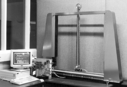

It is virtually impossible to balance a pendulum in the inverted position without applying some external force to the system. The Carriage Balanced Inverted Pendulum (CBIP) system, shown below, allows this control force to be applied to the pendulum carriage. This CBIP is a computer controlled system which provides the control force to the carriage by means of a DC servo-motor through a belt drive system. The outputs from the CBIP rig are carriage position, carriage velocity, pendulum angle and pendulum angular velocity. These are interfaced to a 486 PC which controls the servo-motor. The aim of the study was to stabilise the pendulum such that the position of the carriage on the track is controlled quickly and accurately and that the pendulum is always maintained tightly in its inverted position during such movements.

The project has involved the design and implementation of two types of optimal Proportional-Integral-Plus (PIP) controllers for the, above, large inverted pendulum system. Utilising the TDC approach to control system design, data-based models of the unstable, non-minimum phase, open-loop system were used for Linear-Quadratic (LQ) optimal design of two PIP controllers, both of which out-performed a more conventional, Direct Digital Control (DDC), SVF controller based on a continuous-time, mechanistic model of the system.
As the Inverted Pendulum is open loop unstable it is necessary to design a stabilising controller prior to the undertaking of any identification experiments . The design of an initial stabilising controller can be achieved in a number of ways. In this case, however, an analytical model of the pendulum system had previously been developed and a state variable feedback (SVF) pole-placement controller designed on this basis manages to stabilise the system sufficiently to allow further, data-based identification and estimation studies.
The results of the stabilisong DDC controller showed that, although the DDC controller successfully maintains the stability of the pendulum, the performance in the closed-loop is rather unsatisfactory and the system exhibits a limit cycle type behaviour with considerable steady-state errors to command inputs. Also for large changes of setpoint a ramp function is required as a sudden large step change was found to cause the pendulum to fall.
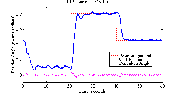
Having identified a SIMO matrix transfer function model for the stabilised closed loop system and with knowledge of the stabilising control, the open loop model for the pendulum can be calculated. Subsequent design of a TDC PIP-LQ controller successfully stabilises the pendulum and provides a superior control to the original stabilising controller. Results of the PIP-LQ controlled system following a position command path are shown below.

For more information you could consult the publication relevant to this topic listed on my main project page (or after September my thesis)
Roger's home page, coupled drives project , pile drive project
[ CRES Home page | Group's Home page | Search | Help | Mail us ]