
The work described herein has been undertaken in collaboration with the "Construction Robotics Group" at Lancaster University.
This page discribes how a control system based upon the Proportional-Integral-Plus (PIP) controller has been designed and implemented on a 1/5 scale model of a piling rig.
 The project came about due to the desire to improve the performance of large pile driving rigs by automation. It is required that the mast is moved to and maintained in a vertical attitude and the position of the mast is controlled to some desired position (before piling commences) under automatic control. The mast verticality is measured by means of a two degree of freedom verticality sensor, whilst the position is taken from a GPS receiver mounted on top of the mast.
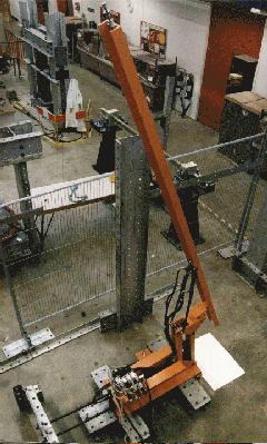
As part of the feasibility study a 1/5 scale "development model" of the piling rig, shown on the right, was built in the Engineering Department at Lancaster University. This was intended as a test bed for the ideas and the control system, where performance could be evaluated and problems revealed and solved before the step to implementation on a full scale pile driver. A schematic of the pile driver scale model is shown below, showing the four inputs to the system which are provided by the hydraulic rams and the four outputs which are two mast angles and two mast positions. Note that the sensors for mast angles and positions are not attached to the rig in this photo.
The TDC strategy is particularly appropriate in this case because of the relatively large sampling period for the system, d = 0.5 seconds, and due to the fact that the system is large and unwieldy making it more difficult to derive a valid mechanistic model given that it’s various characteristics are largely unknown.
Having undertaken the first three steps, the PIP controller is implemented in C++ and run from a custom built embedded PC which is interfaced to the Pile Driver. Tests control systems in such a way that the test rig could perform automatic orientation of the mast, in the same way as is required from a real pile driving rig, prior to initiation of piling. Results of a typical test run with the system operating in this way are shown below.
In these tests, the base of the test rig was tilted such that changing the mast position would alter the angle of the mast (i.e. coupling between the channels is introduced which was unknown at the design stage). This is entirely likely in a real pile driving scenario and gives an indication of how well the system could cope with such "unknown" disturbances.
On the angle variable plots, above, the dashed lines indicate the tolerance required from the verticality when the rig has settled in the desired position. Note however, that the controller almost maintains verticality within tolerance even whilst changing position on a slope (i.e. when changing position is seen as a disturbance to the verticality).
For more information you could look at the pages of the Construction Robotics Group. There should also be some publications forthcoming in the near future, check the publications list. (and after September, my thesis).
Roger's home page, coupled drives project , inverted pendulum project, construction robotics group

![]()


